Wednesday, April 7, 2010

graffiti_screen FINAL PRODUCT

frameworking
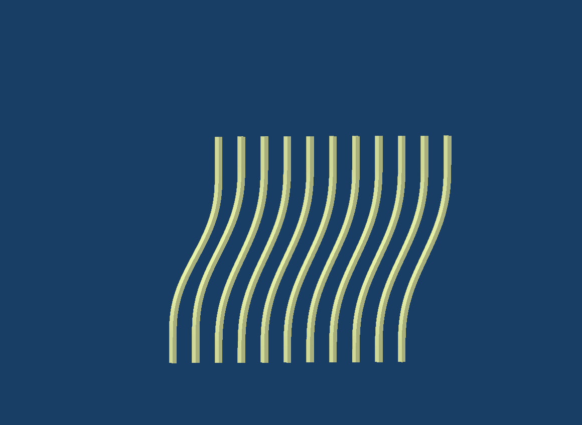
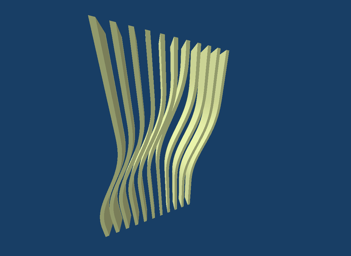
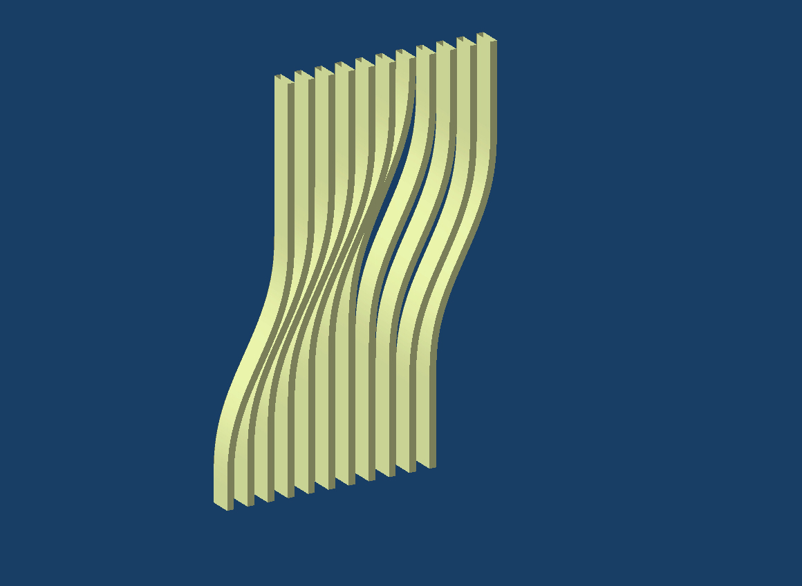
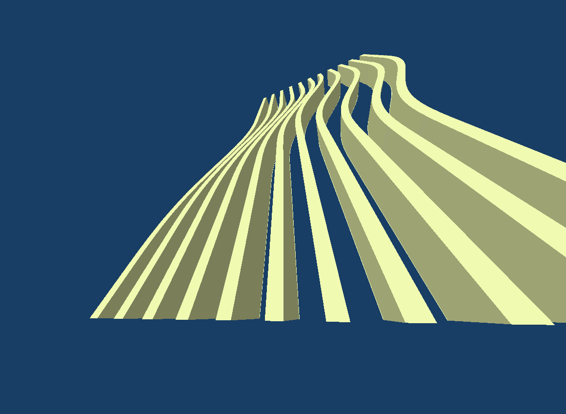
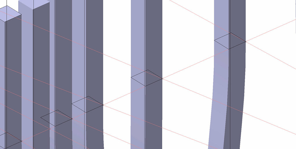
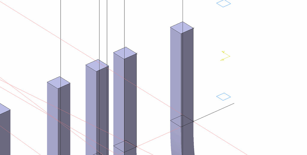
 The framework was setup using a combination of projected curves and global parameters.  Projected curves with points at the intersections were used to create planes that were the basis for sketches.  The global parameters were used to modulate dimensional thickness and heights of modulation.


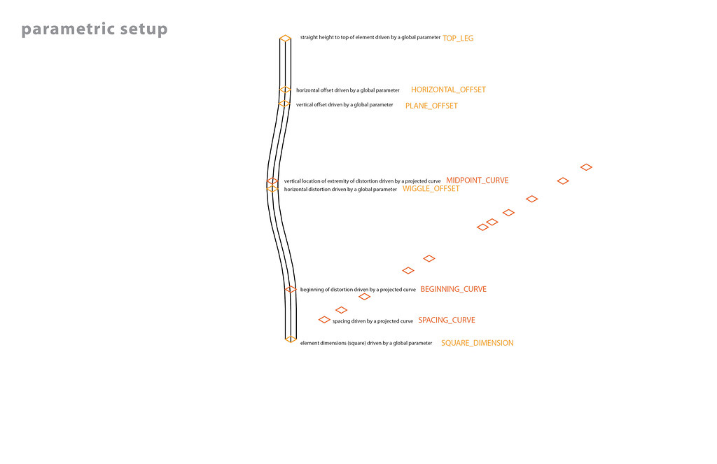
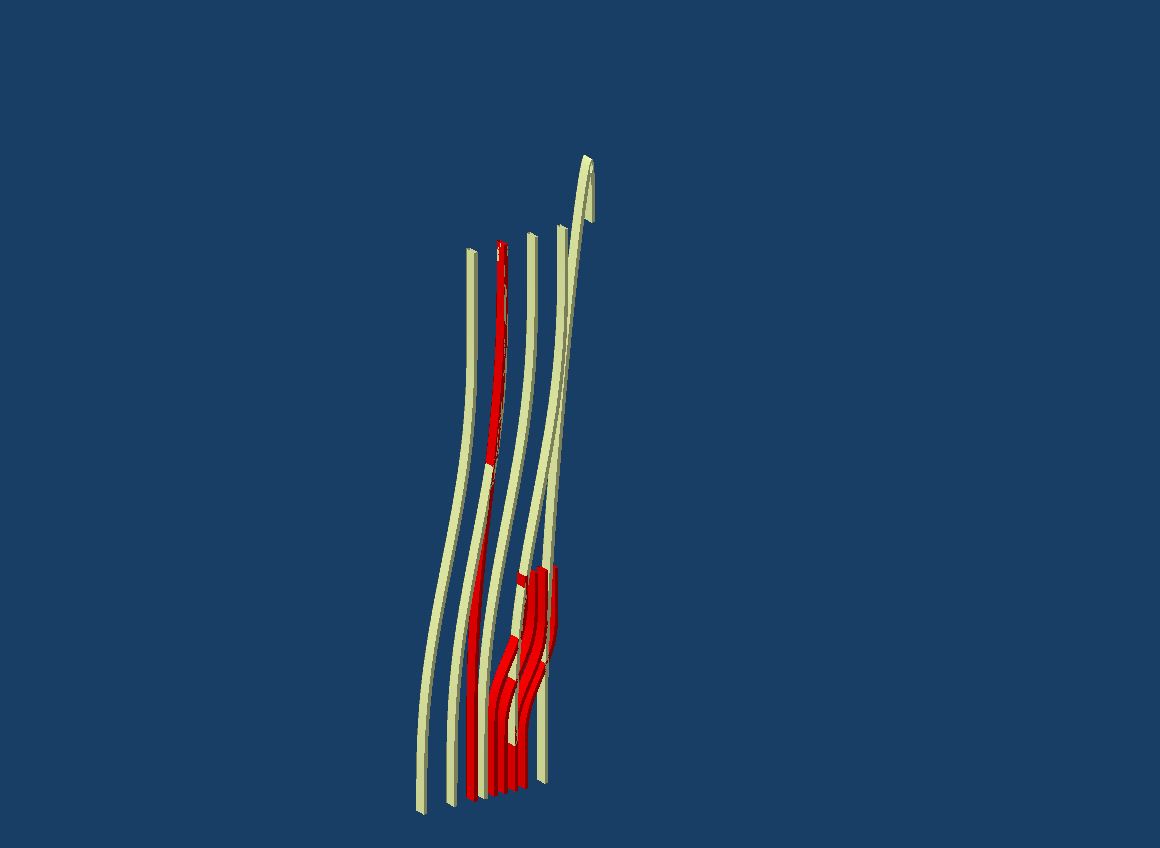
[Color was used to visually keep the planes straight while generating the multi-section solids that form the screen.]

 [Planes were attached directly to the points, or, in some cases attached to parametrically-driven lines out from the points of intersection.]


prototyping
In order to three-dimensionally print the members, four variations were exported to Rhino separately and then compiled into a cut file.


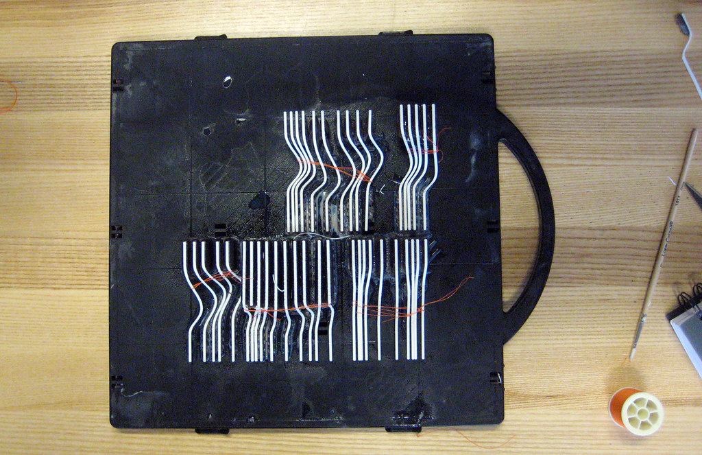
 [With the design intent of lasercutting a base, the members were submitted as separate pieces.  In order to not clog the pipe for the acid bath the members were bundled together using string and tape.] 

 [Neither of the binding solutions worked to keep the pieces together.  One bundle was removed from the acid bath adhered together.]


outputing
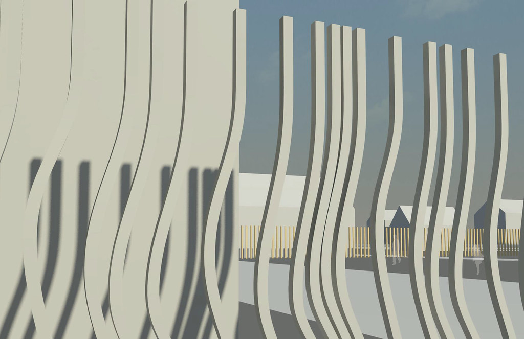
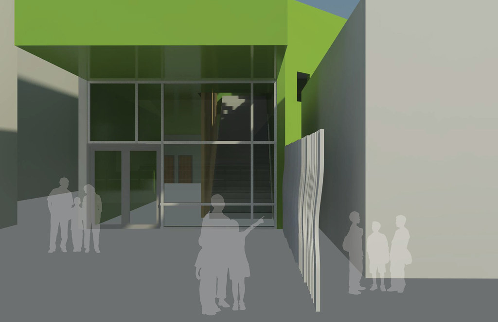
In order to render views of the screen and to show it in the context of my studio project, the digital project file was exported to Rhino as a .igs and then imported into Revit as a .sat file.


documenting
Using the drafting tools in digital project, multiple drawings of the part were generated by setting up a sheet file, updating the model, then refreshing the sheet, and then printing to pdf. 

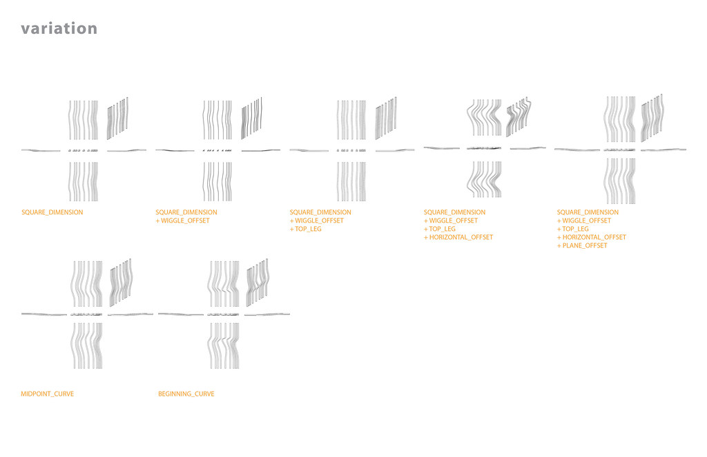
[Multiple iterations of the parametric flexing were edited in Illustrator to change the default lineweight from 1.97pt to .5pt.]

[A still image capture in Digital Project was combined into an animated gif in photoshop to show the active nature of the parametric flexibility.  Approximately two-thirds through the movie, the part is stretched too far and the geometry cannot be created.]

Tuesday, March 30, 2010

graffiti screen: revised framework


This week I started over with the creation of a formwork that would drive the geometry of each piece using four curves.  I projected the spacing onto perpendicular planes, added points coincident with the intersections, and set up parameters to drive offsets.  Potentially this will allow me to morph the entire screen by simply changing numerical values.  I kept the parameters global such that all the powercopies could be controlled at once.  

The problem I'm having right now is that even though I enabled hybrid design, I am not able to powercopy the multi-section solid.  I keep getting an error about ordering.  Maybe I need to shift around my geometrical sets?  

Tuesday, March 23, 2010

screen wall (in progress)


In an attempt to make the swerve in the pieces parametric I created a sketch with a curve to control the heights from the bottom and top.  However, when all the parameters are added the model becomes over-constrained.  I think it might have something to do with the rectangular pattern used to create the grid.

I also setup the named views to eventually create a catalog of conditions.  With more mutations it will create a taxonomy of the parameters in use. 


Tuesday, March 16, 2010

final_framework+powercopies

For my final project, I'm starting by modeling the geometry for a graffiti-proof screen wall.  The idea is that the slats make any tagging illegible and therefore discourages defacement.  


Initial parametric framework and powercopy failures:


Parametric rectangular pattern formwork based on a critical base point that can be modified:


Variations of the spacing and base points to create different patterns:


And then I found the limits of the sweeps:


What I'd like to do next is to use a spreadsheet to drive the parameters of the start and end lengths of the straight runs.  The powercopy is set up such that the straight pieces are controlled and then a curve connects the two endpoints. 

Wednesday, March 10, 2010

final project proposal

For my final project I intend to model a portion of my studio project from this semester.  Currently, it does not involve anything that resembles a building, but my intention fr the rest of the semester is to develop a building that embodies the ideas I have been investigating so far.  

My proposal for the part of the project that is just now wrapping up is about inserting color into a neighborhood in Hamtramck as a means to create productivity in the empty spaces of the city.  This takes on many forms: infrastructure, barrier reassessment, wetland creation, and house painting.  

I want to translate these ideas from disparate non-specific urban proposals into a singular building.  Potentially working in concert with the urban interventions the project would be linked visually with a wider system.  
I intend to use Digital Project to investigate how surface treatments of color translate into material practices.  Specifically, I want to model surfaces that are graffiti-resistant, not through surface finishes, but through their geometry.  The first task will be to create a fence-like structure that is more dynamic. 


Tuesday, February 23, 2010

knowledge patterns


In an attempt to model Maya Lin's Wave Field as a series of instantiated parts that each contained a knowledge pattern, I encountered some resistance from Digital Project.


Attempts to control the high point of the surface in the design file resulted in oddities in the udf.

After multiple attempts to include additional parameters from the beginning of design failed miserably, I decided to take a different path.  


I created ten profiles to drive a multi-section solid.


 I was tempted to add parameters to drive the curves, but wanted to make sure that I could create a UDF from a solid (instead of a surface).


 And then the surface got some color:


The next step would be to find a way to edit the UDF such that the individual waves could be controlled by parameters or values in a spreadsheet.


Additional color studies: 


(p1.Color =   ToString(round(i*(200/sn)))+","+ToString(round(i*(500/cn)))+",500")